As with the usual first-level connection, the wiring of the inter-chassis links (ICLs) may be considered after the fact.
1. ICL Ports
Before we start wiring, let us see what ICL ports are and why they are used.
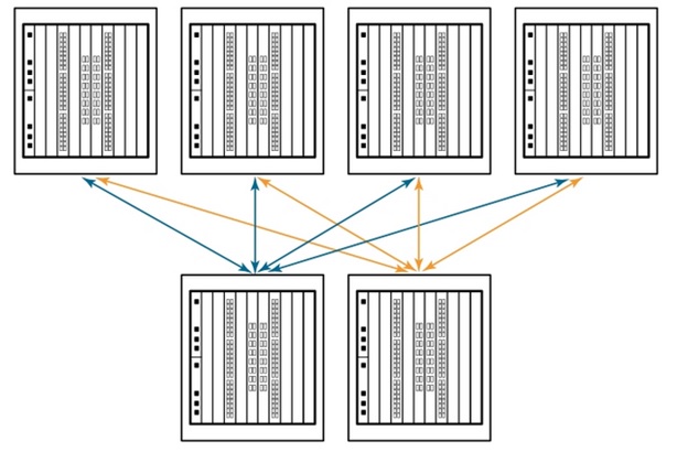
Simply put, the ICL interface can connect two chassis together for redundancy. For those readers who are familiar and experienced with data centers, you may remember the old Daisy Chain topology, which allows you to connect multiple devices in the same link. Think of ICL and Daisy Chain as cousins. See example figure A below.
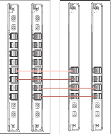
The ICL port can be found on the core routing blade of the chassis. Take a look at Broadcom’s recently launched Gen7 product portfolio, x7-8 has 16 ICL ports per blade (32 in total), and X7-4s has 8 ICL ports per blade (16 in total).
Organizations must adapt to the continued growth of data and use storage environments that can easily scale to meet business needs. Broadcom chassis connection utilizes dedicated ICL to connect up to 12 directors, simplifying the fabric, increasing integration, and reducing complexity and cost at the same time.
Because the ICL connection is located on the core routing blade instead of consuming the ports on the port blade, server and storage connections can use up to 33% of the device ports. This maximizes overall port density with minimal rack space while freeing up front-end equipment ports for server and storage connections. See example figure B below.
2. Cable
Now let’s get to the interesting part: the cable!
X7 uses LWL optical fiber in Gen 7 blades and supports up to 10 kilometers of 32Gb/s cable distance. These ICL kits can provide 7th to 7th generation, 7th to 6th generation, or 7th to 5th generation connections.
For most applications in the data center, you will use shortwave icL. Whether it is the 7th to the 7th generation, with 4x64Gb/s, or the 7th to the 6th generation, with 4x32Gb/s, or the 7th to the 5th generation, with 4x16Gb/s, all supported distances are up to 100 meters.
In all the above scenarios, ICL QSFB requires OM4 12 fiber MTP (MPO) female/female components, which is limited to 100M. MTP is the industry standard MPO connector brand of Conec in the United States.
For longer distances, long-wave ICL will be used. Different from shortwave ICL, starting from Broadcom’s Gen 5 product portfolio (8510-4 and 8510-8s), these products require an LC connector and will use single-mode LC/LC fiber optic patch cords for ICL.
In order to simplify the connection and make it easier to manage, CABL Express recommends the use of structured wiring and patch panels during implementation. Data centers with chassis switches located in separate rows or locations may benefit from this particular strategy. Using LW ICL, your switches can be located on different floors or pods in the data center.
In these cases, using a long cable to directly connect the ICL optics will limit your flexibility when performing any actions, additions, or changes.
Let us optimize the ICL environment through two scenarios.
Scene 1: X6/X7-X6/X7 with SW QSFP ICL Optics
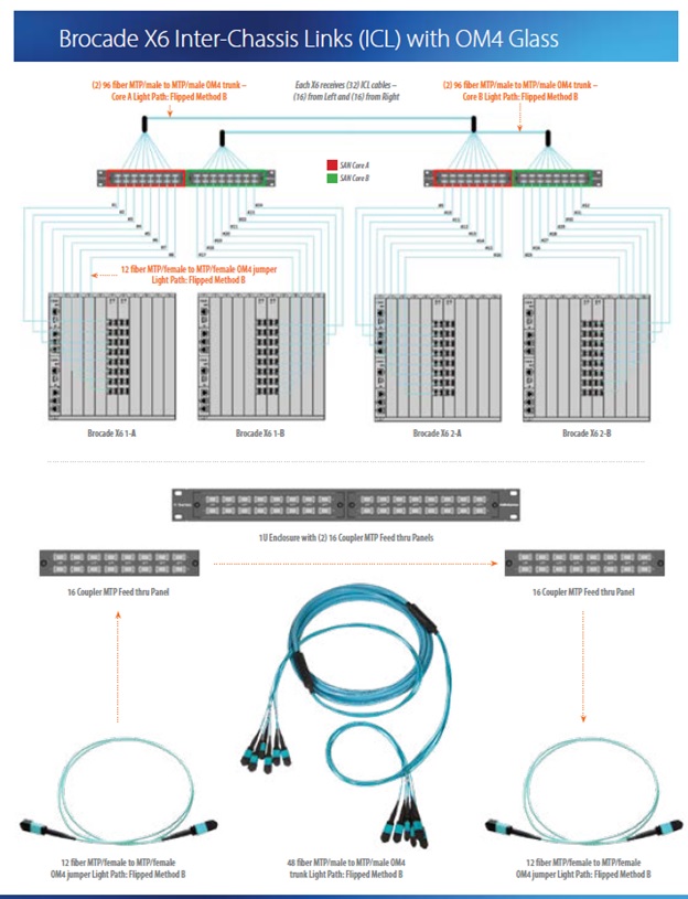
In the design shown on the right, the following CABL Express solutions are used:
- CABL Express 96-Fiber MTP male/MTP male OM4 relay
- This h series 1 u accessory
- 16-MTP adapter board
- CABL Express 12-Fiber MTP bus/MTP OM4 bus
In order to connect in segments, we recommend using 96 fiber optic relay as your “highway”, so you can use a short MTP/MTP patch cord to enter ICL optics.
For example, instead of using 50M ICL components to directly connect to each active port, you can use 96 optical fiber trunks to “forget after setup”.
This allows you to use short jumpers for growth, making it easier to add more ICL ports later. You will reduce future installation time and eliminate risk variables.
Scene 2: X6/X7-X6/X7 with LW QSFP ICL Optics
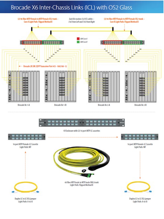
Similar to Option 1 above, Option 2 will use structured wiring and patch panels:
- CABL Express 96-Fiber MTP bus/MTP OS2 SM relay bus
- This h series 1 u accessory
- 16-port MTP/LC card module
- CABL Express duplex LC/LC SM fiber optic patch cord
Similarly, we recommend using 96 fiber MTP/MTP trunks to set up “highways” in this scenario. But since SM LW ICL Optics uses an LC interface, we recommend using MTP/LC box module.
This will allow you to add LC/LC jumpers when adding more ICL ports. As mentioned earlier, due to the limitation of exponential distance, the distance between SAN directors in an environment using SM LW ICL optics is often farther.
3. Never underestimate the importance of cables
When planning and determining the priority of a data center project, budget, resources, time, and many other factors are involved. In the early days, there is no need to spend too much time planning your cable infrastructure.
At that time, the options were very limited, the copper wire was difficult to break, and the cost was very low. Today, data speed and access requirements have increased implementation costs, material and design requirements, as well as mac’s soft costs, troubleshooting errors, and installation issues. When cables are planned and installed according to best practices, the variables of problems and obstacles will be minimized in these high-profile projects.


