The optical fiber is made of glass or plastic. Most of the diameter is about the diameter of a hair, they may be several miles long. Light travels along the center of the fiber from one end to the other, and signals can be applied. Metallic conductors are not as reliable as fiber optics in many applications. Their biggest advantage is bandwidth. Due to the wavelength of light, it can transmit signals that contain much more information than metal conductors (even coaxial conductors). Other advantages include:
- Electrical isolation-the optical fiber does not require a ground connection. The transmitter and receiver are isolated from each other, so there is no ground loop problem. At the same time, there is no danger of sparks or electric shock.
- Free from electromagnetic interference-Optical fibers are not affected by electromagnetic interference (EMI), and they do not emit radiation to cause other interference.
- Low power consumption-This allows for longer cable operation and fewer relay amplifiers.
- Lighter and smaller-Compared with metal conductors with the same signal carrying capacity, optical fibers are lighter in weight and require less space.
The copper wire is about 13 times heavier. Fiber is also easier to install and requires less pipe space.
1. Application of Fiber Optics
Some of the main application areas of optical fiber include:
Communications
- —Voice, data, and video transmission are the most common uses of optical fiber, including:
- -telecommunications
- —Local Area Network (LAN)
- -Industrial Control System
- -Avionics system
- -Military command, control, and communication system
Sensing
Optical fiber can be used to transmit light from a remote light source to a detector to obtain pressure, temperature, or spectral information. Optical fiber can also be used directly as a sensor to measure some environmental influences, such as strain, pressure, resistance, and ph value. Environmental changes can affect the intensity, phase, and/or polarization of the light, which can be detected at the other end of the fiber.
Power Delivery
For laser cutting, welding, marking, and drilling, optical fibers can deliver very high levels of power.
Illumination
A bundle of fibers gathered together with a light source at one end can illuminate hard-to-reach areas, such as the inside of the human body combined with an endoscope. In addition, they can be used as display signs or simply as decorative lighting.
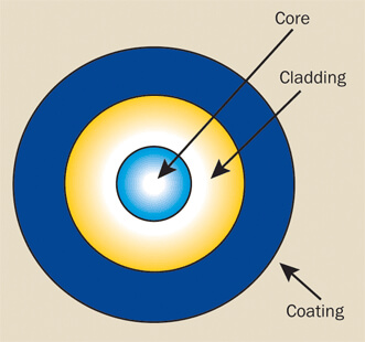
Figure 1. Optical fiber consists of core, cladding, and coating.
2. Optical Fiber Construction
Optical fiber consists of three basic concentric elements: core, cladding, and outer coating (Figure 1). Other materials can be used, depending on the transmission spectrum required. The core is generally made of glass or plastic.
The core is the light-transmitting part of the optical fiber. There are always claddings to protect the core, and they usually have slightly lower refractive indices than the core (usually around 1% lower). This refractive index difference causes the entire internal reflection to occur at the refractive index boundary of the fiber length so that light can travel down the fiber without escaping through the sidewalls.
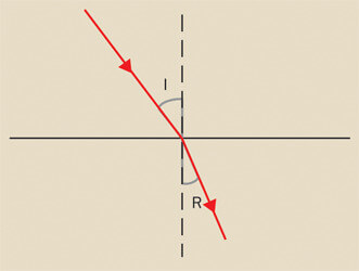
figure 2. A light beam from one material to another material with a different refractive index is bent or refracted at the interface.
The coating usually includes one or more layers of plastic material to protect the fiber from the physical environment. Sometimes for further physical protection, a metal sheath is added to the coating.
The outer diameter of a fiber, the core, the cladding, and the coating typically determine its size. For example, 62.5/125/250 refers to fibers with a 62.5-micrometer diameter core, a 125-micrometer diameter cladding, and a 0.25 mm diameter outer layer.
3. Principle of Optical Fiber
The characteristic of optical materials is their refractive index, called n. An object’s refractive index is the ratio between the rate of change of light speed in a vacuum to the rate of change of light speed in the material. When a beam of light passes from one material to another with a different refractive index, the beam is bent (or refracted) at the interface (Figure 2).
Refraction is described by Snell’s law:
![]()
Among them, nI and nR are the refractive index of the material through which the beam is refracted, and I and R are the incident angle and refraction angle of the beam. If the incident angle is greater than the critical angle of the interface (the fiber is usually around 82°), the light will be reflected back to the incident medium without loss. This process is called total internal reflection (Figure 3).
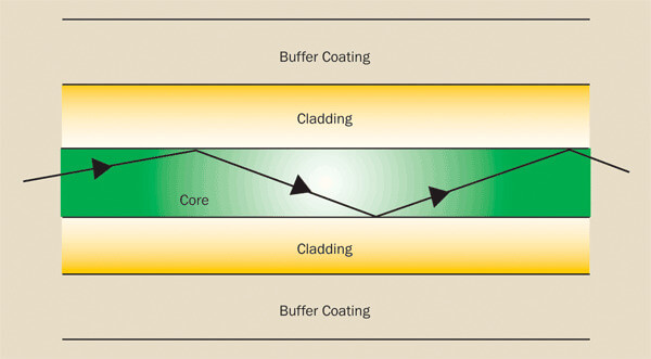
figure 3. Complete internal reflection allows light to stay in the core of the fiber.
4. Optical Fiber Model
When light is guided down an optical fiber (just like a microwave is guided down a waveguide), a phase shift occurs at each reflection boundary. There are finite discrete paths (called modes) on the fiber, and these paths will produce a constructive (phase, and therefore additive) phase shift to enhance transmission. Because when the light beam moves along the length of the fiber, each mode has a different angle to the fiber axis, so each mode passes through the fiber with a different length from input to output. Only one mode, the zero-order mode, passes through the length of the fiber without reflection from the side walls. This is the so-called single-mode fiber. In a given fiber, the actual number of modes that can propagate is determined by the wavelength of the light, the diameter of the fiber core, and the refractive index.
5. Attenuation for Optical Fiber
The intensity of the signal decreases as it propagates in the fiber; this is called beam attenuation. The attenuation measurement unit is the decibel (dB) and the relationship.
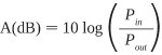
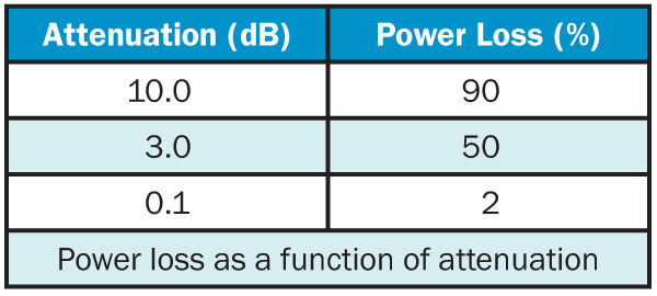
Among them, Pin and Pout refer to the optical power entering and exiting the fiber. The following table shows the power that is usually lost in the fiber with several attenuation values in decibels.
The attenuation of the optical fiber is related to the wavelength. At the extremes of the transmission curve, multiphoton absorption dominates. At a specific wavelength, the attenuation is usually expressed in dB/km. Typical values range from 10 dB/km for 850 nm step-index fiber to a few fractions of dB/km for 1550 nm single-mode fiber.
There are several reasons for fiber attenuation:
- Rayleigh Scattering-The change in the refractive index of the core material on the microscopic scale will cause considerable scattering in the beam, resulting in a large amount of optical power loss. Rayleigh scattering is wavelength-dependent and is not so significant at longer wavelengths. This is the most important loss mechanism in modern optical fibers, usually accounting for 90% of all losses.
The absorption-current manufacturing method reduces the absorption caused by impurities (especially water in the fiber) to a very low level. In the bandpass range of optical fiber transmission, the absorption loss is very small.
- Bending-The manufacturing method can produce tiny bends in the fiber geometry. These bends may cause light to hit below the critical angle inside the core, so light is lost to the cladding material. This can also happen when the fiber is bent into a narrow radius (less than, say, a few centimeters). For a specific bending radius and wavelength, the bending sensitivity is usually expressed in dB/km loss.
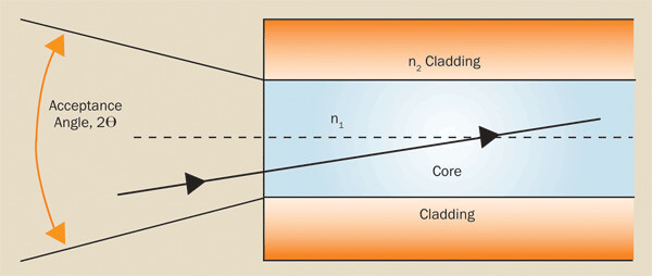
Figure 4. The numerical aperture depends on the angle at which the light enters the fiber and the diameter of the fiber core.
6. Numerical Aperture
The numerical aperture (NA), as shown in Figure 4, is a measurement of the maximum angle at which light enters the fiber and travels along with the fiber. In other words, it can be expressed as follows:
![]()
7. Dispersion
As light pulses traverse the length of the optical fiber, they are broadened or lengthened in time. This is called dispersion. Since the pulses will eventually become very asynchronous, they begin to overlap each other and destroy the data. The chromatic dispersion sets an upper limit for the data-carrying capacity of the fiber. This expansion is motivated by three main factors:
- Dispersion—Different wavelengths propagate at different speeds in the fiber. Because a typical light source provides energy over a series or range of wavelengths, rather than from a single spectral line, the pulse must spread along the length of the fiber. The high-speed laser used for communication has a very narrow spectral output specification, which greatly reduces the influence of dispersion.
- Modal dispersion-different fiber modes reflect at different angles as they go down the fiber. Since the beam path length produced by each mode angle is slightly different, the high-order mode reaches the optical fiber output end after the low-order mode.
- Waveguide dispersion—The secondary cause of dispersion is the geometry of the fiber, which causes the propagation speed of each mode to be different.
8. Bandwidth
The bandwidth refers to the capacity of optical fibers to carry data. It is calculated by multiplying the data frequency by the transmission distance (normally MHz-km or GHz-km).
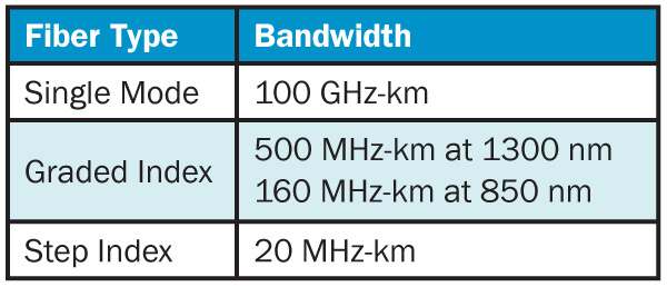
For example, an optical fiber with a bandwidth of 400-MHz-km can transmit 400 MHz data over a distance of 1 kilometer, or transmit 20 MHz data over a distance of 20 kilometers. The main limitation on bandwidth is pulse broadening, which is caused by the modal dispersion and dispersion of the fiber.
Typical values for different types of fibers are as follows:
9. Power Transmission
The power transmitted by the optical fiber (not damaged) is usually expressed by the maximum acceptable power density. The power density is the product of the maximum output power of the laser and the area of the laser beam. For example, a 15 W laser beam is focused on a spot with a diameter of 150 µm, and the resulting power density is
![]()
The output of a pulsed laser (usually measured in millijoules of energy per pulse) must first be converted to power per pulse. For example, the output power of a pulsed laser generating 50 MJ in a 10-ns pulse is
![]()
The power density can be calculated from the spot size.
In order to transmit the absolute maximum energy level to the fiber, the fiber end face must be absolutely smooth and polished, and perpendicular to the fiber axis and beam.
In addition, the beam diameter should not be greater than about half of the core area (or core diameter). If the beam is not properly focused, some energy may overflow into the cladding, which can quickly damage the silicon fibers of the polymer cladding. Therefore, it is best to use silicon-clad silicon fibers in high power density applications.
10. Types of Fiber
There are basically three types of optical fibers: single-mode, multi-mode gradient index, and multimode step-index. They are characterized by the way light propagates in the fiber and depends on the wavelength of the light and the mechanical geometry of the fiber.
Figure 5 shows an example of how they spread light.
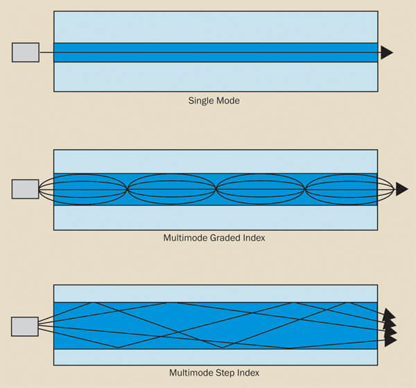
Figure 5 Optical fiber transmission mode.
11. Single-mode
Only the basic zero-order mode is transmitted in a single-mode fiber. The beam passes directly through the fiber without any reflection from the sidewall of the core cladding. The characteristic of single-mode fiber is the wavelength cutoff value, which is related to the core diameter, NA, and working wavelength. Below the cut-off wavelength, higher-order modes can also propagate, which changes the characteristics of the fiber.
Because single-mode fibers only propagate the fundamental mode, modal dispersion (the main cause of pulse overlap) is eliminated.
Therefore, the bandwidth of single-mode fiber is much higher than that of multi-mode fiber. This simply means that the pulses can be transmitted more closely in time without overlapping. Because of this higher bandwidth, single-mode fiber is used in all modern telecommunication systems. The typical core diameter is between 5 and 10 µm.
The actual number of modes that can propagate through the fiber depends on the core diameter, numerical aperture, and wavelength of the transmitted light. These can be combined into normalized frequency parameters or V numbers.
![]()
The radius of the core is A, the wavelength is λ, and the index of the core and cladding is N. The conditions for single-mode operation are:
![]()
The cutoff wavelength is perhaps more useful. This is the wavelength at which the optical fiber allows multi-mode propagation, which can be expressed as:
Usually, the cut-off wavelength of the selected fiber is slightly lower than the required operating wavelength. For lasers commonly used as light sources (with output wavelengths between 850 and 1550 nm), the core diameter of a single-mode fiber is between 3 and 10 μm.
12. Gradual Multimode
The core diameter of multimode fiber is much larger than that of single-mode fiber. Therefore, higher-order modes will also propagate. The core of a graded-index fiber has a radially decreasing refractive index from the center to the cladding interface.
Therefore, light travels faster at the edge of the core than at the center. The travel time of different modes on curved paths is almost the same. This greatly reduces the modal dispersion in the fiber.
Therefore, graded-index fiber has a much larger bandwidth than step-index fiber, but it is still much smaller than single-mode fiber. The typical core diameters of graded-index fibers are 50, 62.5, and 100 µm, respectively. The main application of graded-index fiber is in mid-range communications, such as local area networks.
13. Mutant Multimode
The core of the step-index fiber has a uniform refractive index, up to the cladding interface, where the refractive index changes stepwise at the cladding interface. In step-index fibers, different modes have different path lengths when passing through the fiber, so the distance for data transmission must be kept short to avoid modal dispersion. The core diameter of the step refractive index fiber is 100 ~ 1500 µm. They are ideal for applications requiring high power density, such as medical and industrial laser power transmission.


